Have you ever wondered how exactly a request made from the comfort of your home, on your computer, ends up at a server on some other part of the planet? Through diagrams, I will try to layout what exactly happens when we type an address on our browser, and hit Enter.
The Internet Protocol Suite
There are several models that layout how to visualize an HTTP request making it’s way across the Internet. One such model is the Internet Protocol Suite model. Let’s take a look at how this might look.
Application Layer
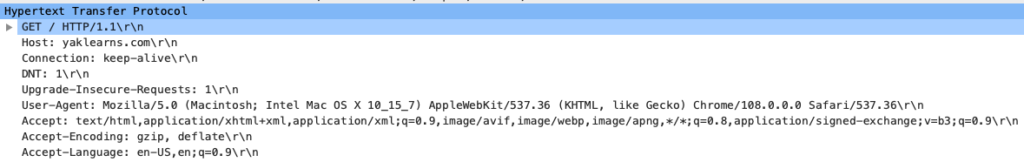
The request starts off as what most of us think an HTTP request looks like. At this level, basic information is put together. Things like: HTTP method, path to hit, encoding type, schema, accepted-encoding, user data, etc.
Transport Layer
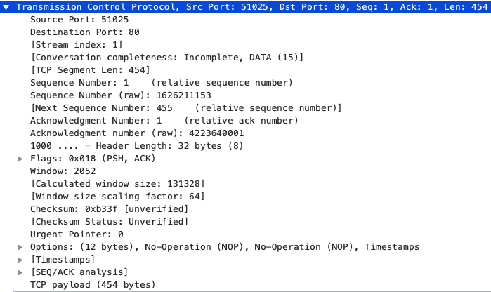
Transport Communication Protocol (TCP) is used by HTTP. TCP breaks up the data into segments and attaches the source and destination ports. Each segment carries a label to identify its order among all of the segments. TCP sends a predetermined number of segments and waits for acknowledgement. If it recieves acknowledgement of successful transmission thus far, it continues with the next batch of segments. If it does not recieve acknowledgement after a set time, it will retransmit the same batch.
Network Layer
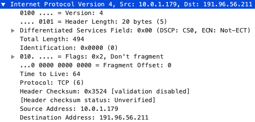
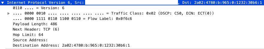
The network layer appends the source and destination IP addresses to the segment. Unlike the MAC address (which we will later see), these values remain constant throughout the transmittion of the data. A segment with the IP header attached is called a packet.
Link Layer
The link layer applies the Address Resolution Protocol (ARP) to determine the MAC address of device we are sending to. This is different than the destination device’s MAC address because a packet will travel through sevel devices before ending up at the last device. At this stage, we refer to the object as a frame.
Physical Layer
Lastly, we have the physical layer. This layer is in charge with taking the frame and breaking it down to raw bits. It then transmits this data via one of three possible mediums: copper cable, radio transmission (WIFI), or light waves (fiber optics). This depends on which interface of the network card the data will be sent out through.
Play by Play
Now let’s take a look at how this will look with an example.
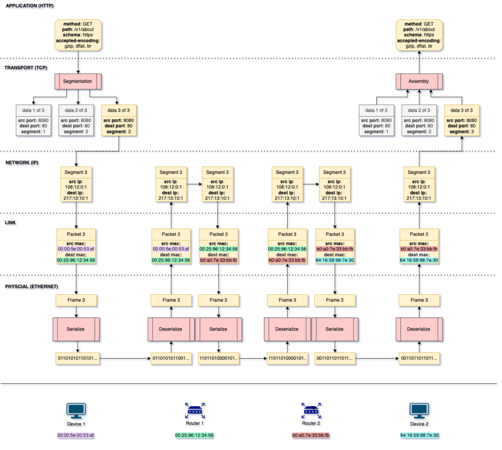
In this example, device 1 is making a HTTP GET request to device 2. TCP takes that GET request and breaks it down to 3 segments. Keep in mind that 3 is arbitraty here. Depending on the size of the HTTP request and the maximum size of a segment, the number of segments generated varies. In this example, we assume that the first 2 segments have already been transmitted. Next, segment 3 gets the IP header appended to it, then the MAC address. The source MAC address identifies the current device, while the destination MAC address identifiers the next device in this packet’s journey, which is the MAC address of router 1. Finally, this frame is serialized into bits and transmitted via the approriate interface of device 1’s network card.
Upon recieving the request in the form of bits, router 1 needs to deserialze the bits to data in order to do 2 things: it verifies that the data was indeed intended for router 1, and it needs to determine who to send the data to next. Upon deserializing the bits into frame 3, router 1 can read the destination MAC address to make sure router 1 is the intended recepient of the data. After validating this, router 1 checks the IP header to extract the destination IP address. By referring to its IP route table, router 1 can determine which device it needs to send this request to. In our example, router 1 is not connected directly to the destination device however, according to its IP route table, router 2 will be able to help this request on it’s jounery to its destination. And so, router 1 modifies the source MAC address to its own, and the destination MAC address to router 2’s MAC address. Lastly, it serializes the frame and sends it to router 2.
Router 2 does the exact same thing as router 1. However, according to router 2’s IP route table, it is connected directly to device 2, whose IP address matches the destination IP address. Router 2 then sends the data directly to device 2, without the need of any more routers.
Upon recieving the bits, device 2 will deserialize the data and validate that it is the intended target of the request by comparing the MAC address and the IP address. It will then inspect the segment to determine that it has all of the segments required to reconstruct the data. Upon reconstructing the data from the 3 segments, device 2 will have recieved the original HTTP request.
DNS Lookup
You might have noticed that we magically plugged in the destination IP address above. As users, it’s difficult for us to remember the IP address of the website we want to visit. We need a way of attaching an easy to remember string to an IP address, and every machine on the Internet should have the ability to find this mapping. This is where DNS lookup comes into play.
To start off, we will start with an high level view of the flow of data. Let’s say that we want to bring up the website: www.yaklearns.com. The flow of data will look as follows:
TODO: diagram of DNS lookup
Similar to sending a letter to a friend, we need the address to which our request will be sent. Unlike sending a letter to a friend, the Internet (be it the public or a private one) does not address devices using common names. Instead, every device on the Internet has an Internet Protocol address, also known as an IP address. There are two IP address standards: IPv4 and IPv6. We will only discuss IPv4 addresses, which take the form A.B.C.D, where A, B, C, and D exist in the range [0, 127]. For this reason, the first thing your computer must do is figure out the IP address for “www.yaklearns.com“. This is called IP resolution.
To resolve the IP address, your computer makes a request to the DNS resolve that it’s configured to. By default, your DNS resolve will be the one provided by your Internet Service Provider (ISP). You can change this, and there are benefits to doing so, however, we will not go down that rabbit whole here.
Upon recieving your request to resolve address “www.yaklearns.com“, the DNS resolver will check it’s cache to see if it has a live record for this address. In order to avoid data going stale, each record in the DNS cache will have a TTL (time to live). When this expires, the record is evicted from the cache.
If the DNS cache contains the record for our address, the DNS resolver will return the IP address to the client / requester. However, if it does not, the DNS resolver will send the request to one of the 13 clusters of root DNS servers.
A root DNS server is a server that contains a list of all of the top level domains. Upon request, it will return the IP address of the TLD that corresponds with the query string sent. In our example, the query string that the root DNS server will help us resolve is “.com”. The root DNS server will return the IP address of the TLD that has information on the “.com” domain.
TODO …
The Request
You can actually see the DNS request by monitoring your traffic using something like WireShark.
Traffic Routing
In our example above, we displayed how a request traverses two routers before reaching its destination. In reality, a request may have to traverse many routers before reaching its destination. So what dictates the route that a frame will traverse?
Each device that connects to other devices has a network interface card (NIC). A NIC allows a device to connect to one or more devices. This connection can be either via a copper cable, a fiber optics cable, or radio waves. A NIC also has a universally unique Media Access Control (MAC) address.
A MAC address …
When a device attempts to send data to another device, it will push the data out of one of the interfaces of the NIC. In order to figure out which interface to push the data through, the device refers to its IP routing table. You can view the IP routing table of your computer using the following command:
# Windows
> ip route
# MacOS
> netstat -rnl